
Deskripsi
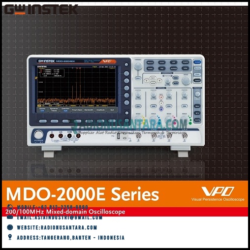
GW Instek MDO-2000E Series Mixed-domain Oscilloscopes
MDO-2000E series is multi-functional mixed domain oscilloscope. The series includes two feature combinations : MDO-2000EG and MDO-2000EX. MDO-2000EG models have a built-in spectrum analyzer and a dual channel 25MHz arbitrary waveform generator and MDO-2000EX models feature a built-in a spectrum analyzer, arbitrary waveform generator, a 5,000 count DMM, and a 5V/1A power supply. The first of its kind, MDO-2000EX is the only oscilloscope to equip with a DMM and a power supply in the T&M industry.
Features
- 200/100/70MHz bandwidth selections ; 2 or 4 channels
- Real time sampling rate for each channel is 1GSa/s (2 channel models)
- Maximum real time sampling rate is 1GSa/s (4 channel models)
- Per Channel 10M memory depth and VPO waveform display technology
- Waveform update rate up to 120,000 wfms/s
- 8“ WVGA TFT LCD display
- Free Frequency Response Analyzer Software
- Maximum 1M FFT provides higher frequency domain resolution measurements
- High ,low and band pass filter functions
- 29,000 segmented memories and waveform search functions
- I2C/SPI/UART/CAN/LIN serial bus trigger and decoding function
- Data log function is able to track signal changes up to 1000 hours
- Network storage function
- Mask test function
- MDO-2000EG equips with a spectrum analyzer and a dual channel 25MHz AWG MDO-2000EX equips with a spectrum analyzer ; a dual channel 25MHz AWG; DMM and power supply
- True RMS measurement in DMM function
Specifications
|
MDO-2102E(G/X) |
MDO-2104E(G/X) | MDO-2202E(G/X) |
MDO-2204E(G/X) |
||
| VERTICAL SENSITIVITY | Channels |
2Ch+EXT |
4Ch | 2Ch+EXT |
4Ch |
| Bandwidth |
DC~100MHz(-3dB) |
DC~200MHz(-3dB) |
|||
| Calculated Rise Time |
3.5ns |
1.75ns |
|||
| Bandwidth Limit |
20MHz |
20M/100MHz |
|||
| Vertical Resolution | 8 bits : 1mV ~ 10V/div | ||||
| Input Coupling | AC, DC, GND | ||||
| Input Impedance | 1MΩ // 16pF approx.. | ||||
| DC Gain Accuracy | ±(3% when 2mV/div or greater is selected ; ± (5%) when 1mV/div is selected | ||||
| Polarity | Normal & Invert | ||||
| Maximum Input Voltage | 300Vrms , CAT I | ||||
| Offset Position Range | 1mV/div ~ 20mV/div : ± 0.5V ; 50mV/div ~ 200mV/div : ± 5V ; 500mV/div ~ 2V/div : ± 25V ; 5V/div~10V/div : ± 250V | ||||
| Waveform Signal Process | + , – , × , ÷ , FFT , User Defined Expression FFT : 1Mpts ; FFT : Spectral magnitude. Set FFT Vertical Scale to Linear RMS or dBV RMS and FFT Window to Rectangular, Hamming , Hanning, or Blackman |
||||
| TRIGGER | Source | Ch1 ,CH2, CH3, CH4, Line, EXT* ; *dual channel models only | |||
| Trigger Mode | Auto (Supports Roll Mode for 100 ms/div and slower), Normal, Single Sequence | ||||
| Trigger Type | Edge, Pulse Width (Glitch), Video, Pulse Runt, Rise & Fall (Slope), Alternate, Time out, Event-Delay (1~65,535 events),Time-Delay (Duration;4ns~10s), Bus | ||||
| Trigger Holdoff Range | 4ns ~ 10s | ||||
| Coupling | AC, DC, LF rej. , Hf rej. , Noise rej. | ||||
| Sensitivity | 1div | ||||
| EXT TRIGGER | Range | ±15V | |||
| Sensitivity | DC ~ 100MHz Approx. 100mV; 100MHz ~ 200MHz Approx. 150mV | ||||
| Input Impedance | 1MΩ ±3%, ~16pF | ||||
| HORIZONTAL | Time Base Range | 1ns/div ~ 100s/div (1-2-5 increments); ROLL : 100ms/div ~ 100s/div | |||
| Pre-trigger | 10 div maximum | ||||
| Post-trigger | 2,000,000 div maximum | ||||
| Time Base Accuracy | ±50 ppm over any ≥1 ms time interval | ||||
| Real Time Sample Rate | Max. : 1GSa/s (4ch model); Per channel 1GSa/s (2ch model) | ||||
| Record Length | 10Mpts/CH | ||||
| Acquisition Mode | Normal, Average, Peak Detect, Single | ||||
| Peak Detection | 2ns (typical) | ||||
| Average | Selectable from 2 to 256 | ||||
| X-Y MODE | X-Axis Input | Channel 1 ; Channel 3* (* : four channel models only) | |||
| Y-Axis Input | Channel 2 ; Channel 4* (* : four channel models only) | ||||
| Phase Shift | ±3° at 100kHz | ||||
| CURSORS AND MEASUREMENT | Cursors | Amplitude, Time, Gating Available; Unit : Seconds (S), Hz (1/S), Phase (Degrees), Ratio (%) | |||
| Automatic Measurement | 38 sets: Pk-Pk, Max, Min, Amplitude, High, Low, Mean, Cycle Mean, RMS, Cycle RMS, Area, Cycle Area, ROVShoot, FOVShoot, RPREShoot, FPREShoot, Frequency, Period, RiseTime, FallTime, +Width, -Width, Duty Cycle, +Pulses, -Pulses, +Edges, -Edges, %Flicker, Flicker Idx., FRR, FRF, FFR, FFF, LRR, LRF, LFR, LFF, Phase | ||||
| CONTROL PANEL FUNCTION | Auto Counter | 6 digits, range from 2Hz minimum to the rated bandwidth | |||
| Autoset | Single-button, automatic setup of all channels for vertical, horizontal and trigger systems, with undo Autoset | ||||
| Save Setup | 20 sets | ||||
| Save Waveform | 24 sets | ||||
| DISPLAY SYSTEM | TFT LCD Type | 8″ TFT LCD WVGA color display | |||
| Display Resolution | 800 horizontal x 480 vertical pixels (WVGA) | ||||
| Interpolation | Sin(x)/x | ||||
| Waveform Display | Dots, Vectors, Variable persistence(16ms~4s), Infinite persistence | ||||
| Waveform Update Rate | 120,000 waveforms per second, maximum | ||||
| Display mode | YT ; XY | ||||
| Display Graticule | 8 x 10 divisions | ||||
| INTERFACE | USB Port | USB 2.0 High-speed host port x 1, USB 2.0 High-speed device port x 1 | |||
| Ethernet Port (LAN) | RJ-45 connector, 10/100Mbps with HP Auto-MDIX | ||||
| Go/NoGo BNC | 5V Max/10mA TTL open collector output | ||||
| Kensington Style Lock | Rear-panel security slot connects to standard Kensington-style lock | ||||
| SPECTRUM ANALYZER SPECIFICATIONS | Frequency Range | DC~500MHz (Max.) (Max. bandwidth ~500MHz uncalibrated) | |||
| Span | 1kHz ~ 500MHz (Max.) | ||||
| Resolution Bandwidth | 1Hz ~ 500kHz (Max.) | ||||
| Reference Level | -50 dBm to +40dBm in steps of 5dBm | ||||
| Vertical Units | dBV RMS; Linear RMS; dBm | ||||
| Vertical Position | -12divs to +12divs | ||||
| Vertical Scale | 1dB/div to 20dB/div in a 1-2-5 Sequence | ||||
| Display Average Noise Level | 1V/div < -50dBm, Avg: 16 ; 100mV/div < -70dBm, Avg: 16 ; 10mV/div < -90dBm, Avg: 16 | ||||
| Spurious Response | 2nd harmonic distortion< 40dBc; 3rd harmonic distortion < 45dBc | ||||
| Frequency Domain Trace Types | Normal; Max Hold; Min Hold; Average (2 ~ 256) | ||||
| Detection Methods | Sample; +Peak ; -Peak; Average | ||||
| FFT Windows | FFT Factor: Hanning 1.44; Rectangular 0.89; Hamming 1.30; Blackman 1.68 | ||||
| AWG SPECIFICATIONS | Channels | 2 | |||
| Sample Rate | 200 Msa/s | ||||
| Vertical Resolution | 14 bits | ||||
| Max. Frequency | 25 MHz | ||||
| Waveforms | Sine, Square, Pulse, Ramp, DC, Noise, Sinc, Gaston, Lorentz, Exponential Rise, Exponential Fall, Haversine, Cardiac | ||||
| Output Range | 20 mVpp to 5 Vpp, High Z; 10 mVpp to 2.5 Vpp, 50Ω | ||||
| Output Resolution | 1mV | ||||
| Output Accuracy | 2% (1 kHz) | ||||
| Offset Range | ±2.5 V ac+dc, High Z; ±1.25 V ac+dc, 50Ω | ||||
| Offset Resolution | 1mV | ||||
| Sine | Frequency Range: 100mHz~25MHz; Flatness (relative to 1kHz): ±0.5 dB <15MHz; ±1 dB 15MHz~25MHz; Harmonic Distortion: -40 dBc; Stray (Non-harmonic): -40 dBc; Total Harmonic Distortion: 1% ; S/N Ratio: 40 dB | ||||
| Square/Pulse | Frequency Range: 100mHz~15MHz; Rise/Fall time: <15ns; Overshoot: <3%; Duty cycle Square: 50% & Pulse: 0.4%~99.6%; Min. Pulse Width: 30 ns; Jitter: 500 ps | ||||
| Ramp | Frequency Range: 100mHz~1MHz; Linearity: 1%; Symmetry: 0~100% | ||||
| FREQUENCY RESPONSE ANALYSIS | Dynamic Range | > 80 dB (typical) | |||
| Input and Output Sources | Channel 1 or 2 (3 or 4 for four channel model) | ||||
| Frequency Range | 20 Hz to 25 MHz | ||||
| Number of Test Points | 10 to 90 points per decade | ||||
| Test Amplitude | 20 mVpp to 5 Vpp into High-Z Fixed amplitude across entire sweep | ||||
| Test Results | Logarithmic overlaid gain and phase plot | ||||
| Manual Measurements | Two pairs of tracking gain and phase markers | ||||
| Plot Scaling | Auto-scaled during test | ||||
| DMM SPECIFICATIONS (MDO-2000EX only) |
Digit Level | 5,000 counts; CAT II 600Vrms, CAT III 300Vrms | |||
| DC Voltage | 50mV, 500mV, 5V, 50V, 500V, 1000V 6 ranges | ||||
| Accuracy | 50mV, 500mV, 5V, 50V, 500V, 1000V ±(0.1% reading + 5 digits) | ||||
| Input Impedance | 10MΩ | ||||
| DC Current | 50mA, 500mA, 10A 3 ranges | ||||
| Accuracy | 50mA~500mA (0.5% reading+0.05mA), 10A ±(0.5% reading + 50mA) | ||||
| AC Voltage | 50mV, 500mV, 5V, 50V, 700V 5 ranges | ||||
| Accuracy | 50mV, 500mV, 5V, 50V, 700V ±(1.5% reading + 15 digits) at 50Hz~1kHz* Amplitude greater than 0.2% of the full scale reading. | ||||
| AC Current | 50mA, 500mA, 10A 3 ranges | ||||
| Accuracy | 50mA, 500mA, ±(1.5% reading + 0.05mA )at 50Hz~1kHz; 10A ±(3% reading + 50mA) at 50Hz~1kHz* Measure range: >10mA | ||||
| Resistance | 500Ω, 5kΩ, 50kΩ, 500kΩ, 5MΩ, 5 ranges | ||||
| Accuracy | 500Ω reading; 5MΩ ±(0.5% reading + 5 digits), 5kΩ, 50kΩ, 500kΩ ±(0.3% + 3 digits) | ||||
| POWER SUPPLY SPECIFICATIONS (MDO-2000EX only) |
Output Channel | CH1 & CH2 | |||
| Output Voltage Range | 1.0V~5.0V | ||||
| Output Current (Max.) | 1A | ||||
| Voltage Step | 0.1V Continuously Adjustable | ||||
| Output Voltage Accuracy | ±3% | ||||
| Ripple and Noise | 50mVrms | ||||
| POWER SOURCE MISCELLANEOUS | Line Voltage Range | AC 100V ~ 240V, 50Hz ~ 60Hz, auto selection | |||
| Multi-Language Menu | Available | ||||
| On-Line Help | Available | ||||
| Time Clock | Time and date, provide the date/time for saved data | ||||
| Operation Environment | Temperature: 0°C to 50°C. Relative Humidity: ≤80% at 40°C or below; ≤ 45%, 41°C ~ 50°C | ||||
| DIMENSIONS & WEIGHT | 384(W) X 208(H) X 127.3(D)mm, Approx. 3 kg | ||||
| ACCESSORIES | Power cord x 1, GTL-110 BNC-BNC cable x 2, GTL-105A Alligator Clip test lead (only on MDO-2000EX), GTL-207A Banana plug test lead (only on MDO-2000EX) GTP-100B-4: 100MHz (10:1/1:1) Switchable passive probe for MDO-2102E(X)/2104E(X)(one per channel) GTP-200B-4: 200MHz (10:1/1:1) Switchable passive probe for MDO-2202E(X)/2204E(X)(one per channel) |
||||
| DATASHEET | MDO-2000E Series | ||||


Ulasan
Belum ada ulasan.